Centrinės tepimo sistemos
Centrinių tepimo sistemų tepalas
Centralizuotos tepimo sistemos plačiai naudojamos pramoninėje ir didelės apkrovos mobiliojoje įrangoje, siekiant sutepti kelis mašinos taškus.
Šios sistemos svyruoja nuo paprasto vieno prievado tepalo iki sudėtingų dviejų eilučių atbulinės eigos blokų, kuriuose naudojami laikmačiai ir aliarmai, kurie patikimai tiekia tepalą į šimtus tepimo taškų.

Dauguma centralizuotų tepimo sistemų skirstomos į dvi kategorijas.
- Pirmoji yra tiesioginė sistema, kurioje siurblys naudojamas tepalui slėgti ir dozuoti jį iki tepimo taško.
- Antrasis ir sudėtingesnis tipas yra netiesioginė sistema, kurioje siurblys spaudžia tepalą. Paskirstymo linijoje įmontuoti vožtuvai naudojami tepalui dozuoti į guolius.
Netiesioginės sistemos toliau skirstomos į du pagrindinius tipus – lygiagrečias ir nelygiagrečias. Lygiagrečiose sistemose, dar vadinamose neprogresyviomis, sistemoje yra slėgis, o dozavimo vožtuvai veikia vienu metu. Lygiagrečios sistemos trūkumas yra tas, kad gali būti sunku nustatyti sugedusį (užsikimšusį) vožtuvą, nes tepalai ir toliau bus išleidžiami per likusius vožtuvus. Siurblio slėgis nepadidės ir nebus jokių išorinių vožtuvo gedimo požymių
Pusiau skystas NLGI 00 tepalas
Konsistencinio centrinio tepalo kiekviena sistemos dalis veikia taip:
- Rezervuaras: suteikia didelį kiekį tepalo, kuris gali būti švarus ir lengvai pasiekiamas sistemai.
- Siurblys: sukuria riebalų srautą ir padidina slėgį linijoje (-ėse). Siurblio dydis skirsis priklausomai nuo atstumo tarp siurblio ir tolimiausio purkštuko.
- Valdiklis: valdo slėgį sistemoje, įjungdamas ir išjungdamas slėgio tiekimo vožtuvus pagal laiką arba ciklą. Jis taip pat gali gauti signalus, rodančius apribotą arba sutrikusį tepalo srautą į guolį.
|
Rūšis |
Darbinės temperatūros, ºC |
Lašėjimo temperatūra, ºC |
Pagrindas |
Panaudojimas, savybės |
|
|
-40 iki +130 |
> 170 |
Mineral + LiHdrx |
NLGI 00 - 000 konsistencijų tepalai.Pusiau skystas centrinių tepimo sistemų konsistencinis tepalas. Sunkvežimių, statybos technikos sistemoms, staklėms. Rusvas. KEP-00K pagal DIN 51825; GP 00 K-40 pagal ISO-L-XDCHB 00; NLGI 00; Willy Vogel aprobacija.
|
|
-40 iki +120 |
180 |
mineral |
Prailginto veikimo, ekstra klasės specialus centrinių guolių sistemų tepalas. Gelsvas. GP0G-40 ir KP0G-40 pagal DIN 51502. NLGI 0. |
|
|
-25 iki +120 |
>155 |
Min/Na |
Lengvai vandeniu nuplaunamas saugios aplinkai sistemai skirtas Natrio tirštiklio pagrindo tepalas. |
|
|
Molyduval Long-Life ZSA MB |
-50 iki +140 |
180 |
Mineral + Li |
Transporto priemonių centrinių sistemų tepalas. Speciali Daimler Benz DBL 6833.00 specifikacija. Taip pat Willy Vogel, MAN 283 Li-P00. Žalias. KP00/000K-50 pagal DIN 51502. NLGI 00 / 000. |
|
-30 iki +120 |
190 |
Mineral + Li |
Staklių centrinių tepimo sistemų sunkiai apkrautiems reduktoriams, dantračiams. GP00G-30 pagal DIN 51502. Gelsvas. NLGI 00. |
|
|
Molyduval Valenzia ZSA |
-35 iki +180 |
190 |
Mineral + Li Komplks |
Aukštatemperatūrinis, padidinto atsparumo drėgmei centrinių tepimo sistemų tepalas. Ypač celiuliozės, popieriaus, tekstilės pramonės įrengimams, dirbantiems padidintų temperatūrų ir drėgmės aplinkoje. Geltonas. KP00/000G-30 pagal DIN 51502. NLGI 00 / 000. |
|
Molyduval Aero 78 |
-70 iki +120 |
180 |
Sintet. Ester |
Specialus sintetinių esterių pagrindo žematemperatūrinis tepalas centrinėms tepimo sistemoms, reduktoriams. Rudas. KPE00/000G-70. NLGI 00 / 000. |
Pusiau skystas plastinis tepalas
Molylub Lycos ZS
Centrinių tepimo sistemų konsistencinis tepalas
Vokietijos kompanijos Molylub sukurtas specialus pramoninis tepalas, gaminamas ličio hidroksisteratinio muilo tirštintojo, bei nuo oksidacijos, susidėvėjimo ir rūdžių apsaugančių priedų pagrindu.
Pritaikymas
- Ypač rekomenduojama slydimo ir riedėjimo guoliams, tepamiems bendra centrine tepimo sistema
- Pavaroms, tepamoms taškiniu tepimu automatiniais lubrikatoriais
- Žematemperatūriniu režimu dirbantiems mechanizmams, kai reikia užtikrinti pakankamą tepalo takumą ir nestingimą net prie žemiausių temperatūrų
- „Multiline“ tipo centrinėms tepimo sistemos
- Komercinio auto transporto, bekelės, statybinės, kelių tiesimo, mobilių betono padavimo siurblių, karinės technikos centrinėms tepimo sistemoms
- Hidraulinių presų sunkiai apkrautų mazgų tepimui Voegel automatine tepimo sistema
Eksploatacinės charakteristikos
Didelė mechaninių krūvių pernešimo geba
Ypatingas takumas ir pumpuojamumasis ilgomis centrinių tepimo sistemų vamzdelių atkarpomis
Labai atsparus vandens nuplovimui
Sumažina energijos sunaudojimą palengvindamas guolio darbinį sukimąsį
Puikus konsistencijos stabilumas svyruojant temperatūroms
Ekolgiškai saugus, sudėtyje nėra agrersyvių bario ir chloro junginių
Specifikacijos ir patvirtinimai
§ Atitinka ir viršyja DIN 51 502 klasifikaciją K00/000K-40
§ Atitinka ISO-L-XCDHB 000 pagal ISO/DIS 6743-9 reikalavimus
§ Willy Vogel AG, Blatt 264 / Bielomatic; Zentralschmiertechnik / MAN 264.0 / 283
Būdingos fizikinės charakteristikos
|
Lycos |
Metodas |
ZS |
|
NLGI koncistencija |
DIN 51 818 |
00 - 000 |
|
Spalva |
|
Rusva |
|
Tirštintojo tipas |
|
Ličio hidroksisteratas |
|
Bazinė alyva (tipas) |
DIN 51 562 |
Mineralinė ISO VG 68 |
|
Lašėjimo pradžios taškas,°C |
DIN ISO 2176 |
> 170 |
|
Kūginis įsiskverbimas @ 25°C 0.1mm |
DIN ISO 2137 |
430 - 460 |
|
Oksidacinis atsparumas , bar |
DIN 51 808 |
0,2 |
|
Darbinės temperatūros,°C |
|
-40 iki +130 |
|
Pumpavimas ilga atkarpa |
|
Ypač Geras |
Patarimai : Informaciją apie alyvos panaudojimą, nenurodytą šiame aprašyme, galite gauti iš vietinio Molylub atstovo Pramonei : tel. (682)29 049 ar el-paštu : info@mechanica.lt
Centralized Grease Lubrication Systems
Brad Jeffries
Centralized grease lubrication systems are widely used in industrial and heavy-duty mobile equipment applications to lubricate multiple points on a machine. These systems range from a simple single-port lubricator to complex dual-line, reversing units employing timers and alarms to deliver grease reliably to hundreds of grease points.
The design parameters of centralized grease systems include the volume and frequency of grease required at each point, the number of points requiring grease, operating conditions, pump pressure, line diameter and distance to the grease points. When used and maintained properly, centralized grease systems can help enhance technician productivity and simplify equipment maintenance processes. The following is a comprehensive overview of centralized grease systems and the benefits they offer, the various types, concerns to watch out for and tips on how to maintain them properly.
Advantages of Centralized Grease Lubrication Systems
Centralized grease systems are designed principally to make the work environment safer for maintenance personnel by simplifying the process of accessing remote grease points, especially in confined spaces, when equipment is in operation. However, the primary benefit is derived from the continuous application of small amounts of grease resulting in improved equipment life, due to the uniform supply of grease.
Hand application is typically performed infrequently and may result in uneven amounts of grease being applied, which can lead to overgreasing resulting in damaged seals and elevated bearing temperatures caused by grease churn.
It is important for maintenance professionals to realize that many centralized grease systems have long lines, precise metering valves, fittings and numerous connections that can malfunction due to vibration, air entrainment and other environmental impacts. Thus, carefully monitoring and maintaining the systems on a consistent basis is critical.
Types of Centralized Grease Systems
Centralized grease lubrication systems are designed to lubricate the broadest range of stationary and mobile equipment. As the lubrication application becomes more complex, the design of the system also becomes more complex as additional features are added.
Most centralized grease systems fall into two categories. The first is a direct system in which a pump is used to pressurize the grease and meter it out to the application point. The second and more complex type is an indirect system in which a pump pressurizes the grease. Valves built into the distribution line are then utilized to meter the grease into the bearings.
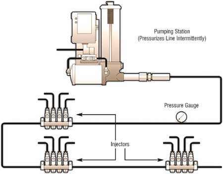
Indirect systems are further broken down into two basic types, parallel and nonparallel. In parallel systems, also known as nonprogressive, the system is pressurized and the metering valves operate simultaneously. The disadvantage of a parallel system is that it can be difficult to identify a failed (blocked) valve, as grease will continue to be dispensed through the remaining valves. Pump pressure will not increase and there will be no outward sign of a valve failure (Figure 2).

Figure 2. Single-line Parallel System
Courtesy of Lincoln Industrial
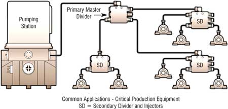
In nonparallel systems, also known as progressive, the metering valves are installed in-line. After the system is brought up to pressure, the first valve operates. Grease then flows through it to the next valve in line. In this setup, if one valve fails, the entire system fails resulting in increased pressure at the pump and no grease consumption. No other obvious problems can be used to quickly identify the exact point of failure (Figure 3).

Figure 3. Single-line Progressive System
Courtesy of Lincoln Industrial
Parallel and nonparallel systems can be further broken down into single- and dual-line systems. Today, the most common type of centralized grease system is the indirect single-line system, accounting for more than 50 percent of the market. For single-line machines, injectors represent the key to quality performance. In single-line systems, injectors are responsible for metering the correct amount of grease to the bearing or other surfaces requiring grease lubrication. When advancing to a new cycle, one must always vent the injectors.
The other type of system, the dual- or two-line system, uses two supply lines to provide grease to the injectors. A four-way valve is used to direct grease alternately to each of the grease lines while relieving pressure on the other line. The second line provides a safety margin but involves additional cost and complexity related to installation.
There are a number of ways to control both the single- and dual-line systems. The valves can be operated manually, cycled by a timer or controlled by a counter that measures grease flow.
Various strainers, filters, alarms and monitoring devices may also be included in the system. These systems are set up in one, two or three stages, depending on the number of lubrication points.
Machinery Lubrication (1/2005)


